2-Dimension Parity Check in Computer Network
2-Dimension Parity Check in Computer Network
The secure transfer of data is crucial in the world of computer networks. Data might experience mistakes as it moves between different network nodes, which can compromise its integrity and make it unusable. Error detection techniques are used to ensure the accuracy and dependability of data transmission to overcome this difficulty. A reliable procedure that improves the integrity of transmitted data is the 2-Dimensional Parity Check.
In computer networks, where data travels across great distances and comes into contact with multiple potential sources of corruption, error detection is essential. Errors can be introduced into the data being transferred by several sources, including electrical interference, transmission line noise, and device faults.
It's crucial to find these flaws to maintain the accuracy of the data and the general effectiveness of network connection.
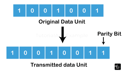
A widely used technique for error detection in computer networks is parity checks. The goal of parity is to transmit data with an additional bit that can be utilized to identify problems when they are received. Based on the amount of set bits (binary value of 1) in the data, this extra bit known as the parity bit is determined. It is known as even parity if the number of set bits is even, and odd parity if it is odd.
- Although 1-Dimensional Parity Checks offer a fundamental level of error detection, they are not without their drawbacks. Only mistakes in a single dimension, such as a single row or column in a data matrix, can be found using 1-Dimensional Parity Checks. However, they are prone to specific mistakes that might go unnoticed. For instance, the parity check might not be able to distinguish between two errors that happen in separate bits inside the same row or column.
- 2-Dimensional Parity Checks were created to address these issues. 2-dimensional parity checks may concurrently detect mistakes in both rows and columns, in contrast to their 1-dimensional equivalents. This greatly improves their robustness and dependability in spotting faults and consequently the integrity of sent data.
An essential component of data communication in computer networks is error detection. Various errors might happen during data transfer, which could result in information that is distorted or wrong. To find and fix these problems and maintain the integrity and dependability of the sent data, error detection techniques are used. Implementing parity checks is one common way for error detection.
Types of Errors
Many different types of errors can happen in computer networks, including transmission line noise, interference, hardware problems, and even software problems. Typical mistakes that happen during data transfer include:
- Single Bit mistake: This kind of mistake happens when one bit is changed while being transmitted. Electrical noise or interference in the communication channel are two potential causes.
- Burst Error: A burst error is a series of errors that occur one after another in a data stream. These errors often come from physical flaws that influence a group of bits, including signal attenuation or interference.
- Random Error: Random errors are intermittent and unexpected, impacting single bits at various locations across the data stream. They may be brought on by brief interruptions in communication or electronic noise.
A typical method of fault detection in computer networks is parity checks. The idea of parity is adding an extra bit to the data being transferred to detect problems when they are received. Based on the quantity of set bits (binary value of 1) in the data, the parity bit is determined. Two kinds of parity are frequently used:
- Odd Parity: By setting the parity bit, odd parity causes all set bits (including the parity bit) to be odd. For instance, the parity bit is set to 1 to make the total odd if the data has an even number of set bits.
- Even Parity: In even parity, the parity bit is set to increase the number of set bits overall (including the parity bit) even.
Methods for Detecting Errors
In computer networks, various more error detection techniques are used in addition to parity checks to guarantee the accuracy of data delivery. Among the often-employed methods for error detection are given below:
- Parity Check: A simple and popular method of error detection is parity check. It includes incorporating a parity bit—an additional bit—into a data unit. To guarantee even or odd parity, the parity bit is set in such a way that the total number of 1s (for odd parity) or 0s (for even parity) in the data unit, including the parity bit, is always even. The recipient runs a parity check after getting the data unit to see if there were any transmission mistakes. An error is recognized if the quantity of 1s or 0s does not match the predicted parity.
- Checksum: Another well-liked error detection technique is a checksum, which creates a checksum value depending on the sent data. The data is subjected to a mathematical process to determine the checksum value. This checksum value is sent together with the data unit by the sender. The recipient computes the checksum again using the same procedure after receiving the data and compares it to the received checksum. The data is regarded as error-free if they agree. Otherwise, a mistake is found. To guarantee data integrity, network protocols like UDP (User Datagram Protocol) frequently use checksums.
- Cyclic Redundancy Check (CRC): A reliable error detection method utilized in many different network protocols and storage systems is the CRC. It entails utilizing a specified generating polynomial to perform polynomial division on the data to be communicated in this manner. The data unit is appended with the CRC remainder, which is the remaining portion of the division operation. Using the data received and the generator polynomial, the same polynomial division is carried out at the receiver's end. No errors are found if the obtained remainder is zero. Otherwise, a mistake is found. High error detection capabilities are offered by CRC, which also resists some faults.
- Hamming Code: Data transmission single-bit faults can be found and fixed using the error detection and correction method known as Hamming code. According to predetermined rules, superfluous bits are added to the original data unit. For error identification and correction, these redundant bits offer more information. Hamming code uses the location of parity bits to find and locate faults. The redundant bits can be used by the receiver to repair the incorrect bit if a mistake is found. In memory systems and communication protocols where error correction is critical, hamming code is frequently utilized.
Limitations of 1 Dimensional Parity Check
- Limited Error Detection Capabilities: The 1-Dimensional parity check's poor capacity to detect errors is one of its key drawbacks. Only single-bit mistakes in the sent data can be found using this method. A data unit may have numerous bit defects, which the parity check may not be able to identify. For instance, the parity check won't pick up on bit errors if two bits are flipped during transmission, resulting in an even number of mistakes. This is because the number of flipped bits remains constant. Due to this restriction, a 1-Dimensional parity check is useless in conditions where many errors are likely to happen, for as in settings with a lot of interference or noise.
- Lack of Error Localization: The difficulty of 1-Dimensional parity checks to precisely locate the location of a mistake within the data unit is another drawback. When an error is found, the parity check can only show that there is an error; it cannot show which specific bit(s) are affected. Due to the recipient's need for retransmission or other error-correction methods to recover the proper data, mistake correction becomes more difficult. The effectiveness of error correction is dramatically decreased in big data units without accurate error localization.
- Vulnerability to Burst Errors: Burst errors, which are a series of errors that happen quickly in the data stream, might affect 1-dimensional parity checks. The parity check may not catch a burst error if it affects many bits in a data unit. Burst mistakes that retain the overall parity may go undetected since the parity bit only examines the overall parity of the data unit. In communication networks where data corruption frequently happens in clusters, burst mistakes are frequent. Due to their capacity to identify and repair burst mistakes, more sophisticated error detection techniques like cyclic redundancy check (CRC) are recommended under such circumstances.
Concept of 2-Dimensional Parity Check
The foundation of a 2-Dimensional Parity Check is the idea of adding extra parity bits to a data unit in a matrix format. Additional parity bits are calculated for each row and column once the data unit is partitioned into rows and columns. To generate a matrix with parity information, these parity bits are added to the data unit. The recipient does parity checks on both the rows and columns after receiving the data unit to look for errors. An error is noticed if the row parity or column parity contains any discrepancies.
Advantages
- Additional Error Detection Capability: When compared to 1-Dimensional Parity Check, 2-Dimensional Parity Check has a better ability to discover errors. This technique can identify more errors, such as single-bit errors, multiple-bit errors, and burst faults that affect particular rows or columns by taking into account both row and column parities. 2-Dimensional Parity Check is more reliable in contexts where mistakes are more likely to occur owing to noise, interference, or transmission problems because of its extensive error detection capability.
- Punctual Localization of Errors: Contrary to 1-Dimensional Parity Check's restrictions, 2-Dimensional Parity Check has the benefit of accurate error localization. The parity checks on rows and columns can help pinpoint the precise row(s) and/or column(s) where an error occurred when one is identified. This identifies the precise location of the damaged bits and enables effective error correction. The effectiveness of error recovery is increased overall by precise error localization, which lowers the requirement for entire data units to be retransmitted and makes it possible to use targeted error correction methods.
- Detection of Burst Errors: Burst errors, which are a cluster of successive errors that occur in the data stream, can be found using the 2-Dimensional Burst Error Detection Parity Check. Burst errors that span numerous rows or columns can be found using the combination of row and column parity checks. Burst errors can be found and identified by finding patterns of mistakes within the matrix structure, ensuring the accuracy of the sent data. This is crucial in situations like wireless communication or noisy transmission channels when burst errors are frequent.
Block Parity
Block parity, often referred to as horizontal parity, is breaking the data up into segments or blocks and determining the parity for each segment. Based on the binary values of the data bits within the block, the parity bit is determined. A data unit with parity information is then created by appending the calculated parity bit to the block. The recipient parity checks each block of the data unit after transmission and contrasts the received parity bit with the newly calculated parity. An error is found if there is a mismatch.
When data units are fixed in size and can be separated into equal blocks, block parity is advantageous. It offers a quick and effective technique to find problems inside each block. Block parity, however, does not provide accurate error localization inside the block. If an error is found, the full block must be sent again or fixed using alternative error-correction methods.
Row/Column Parity
By taking into account parity tests on both the row and column dimensions, row/column parity, sometimes referred to as vertical parity, increases the error detection capabilities. The data is not broken up into blocks but rather is set out in a matrix style with rows and columns. Based on the binary values of the relevant bits, parity bits are calculated for each row and column. The column parity bits are attached as an additional column at the end of the matrix, and the row parity bits are appended to the end of each row.
The recipient conducts separate parity checks on the rows and columns during transmission. It does the same for the column parity bits as it does for the received row parity bits when comparing them to the recalculated parity for each row. Errors are present if there are any parity problems. Row/column parity has the benefit of providing accurate error localization inside the matrix structure. Error repair can be targeted and effective if the specific row(s) and/or column(s) with parity discrepancies are identified.
Both block parity and row/column parity are efficient at spotting transmission problems in data. The type of data and the application's particular requirements will determine which of the two strategies is best. Block parity is appropriate for data units with a defined size, but row/column parity is more flexible and enables accurate error localization. These error detection approaches can help network systems increase the accuracy and dependability of data transfer.
Practical Application of 2-Dimensional Parity Check
- Data storage systems: 2-dimensional parity check is crucial for guaranteeing data integrity in storage systems like hard drives and RAID configurations. Blocks of data are separated by storage systems, and each block's parity bits are calculated while taking both row and column parity into account. This makes it possible to find and fix mistakes made during the data storage and retrieval procedures. Storage systems that use 2-dimensional parity checks can spot flaws and fix them, protecting against data loss and guaranteeing the accuracy of the information that is stored.
- Network Protocols: To increase the dependability of data transmission, a 2-dimensional parity check is frequently employed in network protocols. Parity bits are added to data packets in systems like Ethernet to find transmission faults. The estimated parity bits at the receiver's end can be examined to look for faults and take the necessary action. This is especially important in settings with plenty of noise or interference, where mistakes are more prone to happen. Network protocols that incorporate 2-dimensional parity checks serve to maintain data integrity and guarantee reliable communication.
- Digital Communication: To provide error-free data transfer, a 2-dimensional parity check must be integrated into digital communication systems. A 2-dimensional parity check offers a method to spot and fix problems in applications like satellite communication or wireless communication, where noise and signal distortions might compromise data integrity. By comparing the estimated parity bits to the data received, the receiver can identify mistakes brought on by interference, channel noise, or transmission problems.
- Barcode scanning: In sectors including retail, logistics, and healthcare, barcodes are frequently utilized for product identification. A 2-dimensional parity check is frequently used to assure correct barcode scanning. Parity bits are used as redundant information in barcode symbols. The parity bits are examined after a barcode scan to make sure the scanned data adheres to the predicted pattern. A disparity indicates a scanning error and necessitates rescanning or error handling if it is found. The use of 2-dimensional parity checks in barcode scanning systems reduces errors in point-of-sale, shipping, and inventory management procedures.
- Memory Error Detection: 2-dimensional parity check is used in computer memory systems, such as RAM, to identify and fix memory operation faults. Parity bits are used in memory modules to store extra details about the data that is being saved. The parity bits are compared to the data being read from memory to find any single-bit errors that might have happened during storage or retrieval. The integrity of crucial data in memory-based applications can be ensured if a mistake is found by applying the proper error correction procedures.
- File transfer and storage: It's important to protect the integrity of the files being moved or stored during file transfer and storage. Errors caused during file transfer or storage can be found by using a 2-dimensional parity check. The file data's parity bits are calculated, and at the receiver's end, the parity bits are compared to the data received. If a mismatch happens, it means mistakes are present and calls for proper responses like retransmission or error management. This use of a 2-dimensional parity check contributes to the continued accuracy and dependability of stored or transferred files.
Challenges and Limitations of 2-Dimensional Parity Checks
- Limited Error Detection Capability: 2D parity checks may have trouble identifying multiple faults that occur in the same row or column, despite their effectiveness in detecting single-bit errors within rows and columns. The parity check may not catch numerous faults that occur in complementary places, leading to erroneous indications of error-free data. Due to this restriction, 2D parity checks are less suitable for applications where it is likely that many errors may occur.
- Error Correction Capability: One of the main drawbacks of 2D parity checks is their inability to fix errors. They do not offer techniques for automatic error correction, merely the ability to detect the presence of faults. Due to this constraint, accurate data recovery requires the use of 2D parity checks in conjunction with error correction techniques like retransmission or more sophisticated error correction codes.
- Computable Complexity: The use of 2D parity checks necessitates more computing power. For large datasets in particular, the generation of parity bits for each row and column increases processing overhead. The performance of systems can be impacted by the computational complexity of 2D parity checks, particularly in real-time applications or on devices with limited resources where efficiency is crucial. The time and computational demands for calculating and verifying parity bits rise together with the size of the data matrix, potentially compromising the system's responsiveness and effectiveness.
- Limited Scalability: With bigger data matrices, 2D parity tests may experience scalability issues. The time and processing resources required for parity bit calculation and verification considerably increase as the number of rows and columns rises. The scalability of 2D parity checks could be constrained by the amount of computing power available and the application's timing restrictions. Alternative error detection and correction techniques, like checksums or cyclic redundancy checks (CRC), may provide better scalability in situations where high-speed processing or real-time data transmission is required.
- Vulnerability to certain types of errors: Despite their effectiveness in discovering single-bit errors, 2D parity checks may not be as reliable in spotting some other sorts of defects. Burst faults, in which several consecutive bits are corrupted, for instance, might not be noticed if they have little impact on the parity bits within certain rows or columns. Similarly, 2D parity checks may not be able to detect errors that occur in patterns spanning numerous rows or columns, which restricts their ability to identify specific error patterns.
- Increased Overhead: In terms of storage requirements, 2D parity tests add more overhead. The total amount of data must be stored since the parity bits must also be kept with the original data. This extra storage overhead may reduce storage capacity, especially in situations where storage resources are few. Additionally, the use of parity bits in data transmission necessitates a larger bandwidth allocation, which has an impact on the effectiveness of data transmission protocols and systems with restrictive communication channels.
- The trade-off between Efficiency and Error Detection: When implementing 2D parity checks, there is a trade-off between computing efficiency and the capacity to identify errors. The error detection capability may be improved by using more sophisticated error detection techniques or by using more parity bits, but this comes at the cost of greater computational complexity and overhead. Based on the particular needs and limitations of the system, the trade-off between efficiency and error detection should be carefully considered.