Interfacing DAC with the 8051 Microcontroller
A wide range of applications calls for microcontrollers, including measuring and controlling physical quantities like temperature, pressure, speed, and distance.
In these systems, the microcontroller creates digital output, but the controlling system only accepts analogue signals, necessitating the usage of DACs, which can translate digital data into a corresponding analogue voltage.
A typical device for converting pulses to analogue signals is the digital to analogue converter (DAC). Analogue signals can be created from digital signals using two different techniques, which are the binary-weighted approach and the R/2R ladder method.
The MC1408 (DAC0808) Digital to Analog Converter will be used in this article. This chip employs the R/2R ladder technique. This approach is capable of far greater precision. By its resolution, DACs are evaluated.
The quantity of binary inputs affects resolution. The most frequent numbers of inputs are 8, 10, 12, etc. The number of information determines the DAC's resolution. As a result, there are 2n analogue levels for every n digital input pins. Two hundred fifty-six(256) distinct voltage levels are available in an 8-input DAC.
The MC1408 DAC (or DAC0808)
The digital inputs are transformed into the current in this chip. By attaching a resistor to the output to change the current into voltage, Iout, the output current is identified. The reference current Iref and the binary integers at DAC0808's input pins D0 through D7, where D0 is the LSB and D7 is the MSB, essentially determine the total current given by the Iout pin. The role of Iout is demonstrated in the following formula.
Iout = Iref (D7/2 +D6/4 +D5/8 +D4/16 +D3/32+D2/64+D1/128+D0/256)
The input current is Iref. Pin 14 must be attached to this. Iref is often used as 2.0 mA.
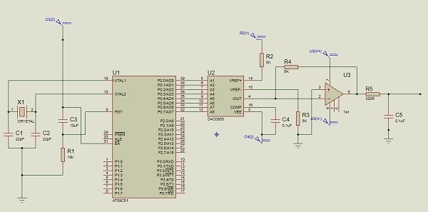
We attach the Iout pin to the resistor to convert the current to voltage. However, as the input resistance of the load would also influence the output voltage in practice, it can lead to inaccuracies. As a result, the Iref current input is essentially isolated by coupling it to an Op-Amp with a 5K=Rf feedback resistor. You can adjust the feedback resistor's value to suit your needs.
Sine Wave generation with DAC and an 8051 microcontroller
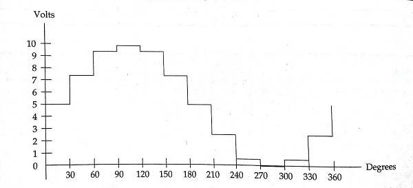
We first need a look-up database to describe the magnitude of the sinusoidal value of an angle between 0° and 360° to generate sine waves. From -1 to +1, the sine function is variable. Only integer values are usable for DAC input in the table. In this example, we'll determine the values from degree to DAC input in steps of 30 degrees. For the DAC output, a full-scale voltage of 10V is assumed. The voltage ranges can be calculated using this formula.
Vout = 5V + (5 ×sinθ)
| Angle (in θ ) | sinθ | Vout (Voltage Magnitude) | Values sent to DAC |
| 0 | 0 | 5 | 128 |
| 30 | 0.5 | 7.5 | 192 |
| 60 | 0.866 | 9.33 | 238 |
| 90 | 1.0 | 10 | 255 |
| 120 | 0.866 | 9.33 | 238 |
| 150 | 0.5 | 7.5 | 192 |
| 180 | 0 | 5 | 128 |
| 210 | -0.5 | 2.5 | 64 |
| 240 | -0.866 | 0.669 | 17 |
| 270 | -1.0 | 0 | 0 |
| 300 | -0.866 | 0.669 | 17 |
| 330 | -0.5 | 2.5 | 64 |
| 360 | 0 | 5 | 128 |
SOURCE CODE
#include<reg51.h>
sfr DAC = 0x80; //Port P0 address
void main(){
   int sin_value[12] = {128,192,238,255,238,192,128,64,17,0,17,64};
   int i;
   while(1){
      //infinite loop for LED blinking
      for(i = 0; i<12; i++){
         DAC = sin_value[i];
      }
   }
}